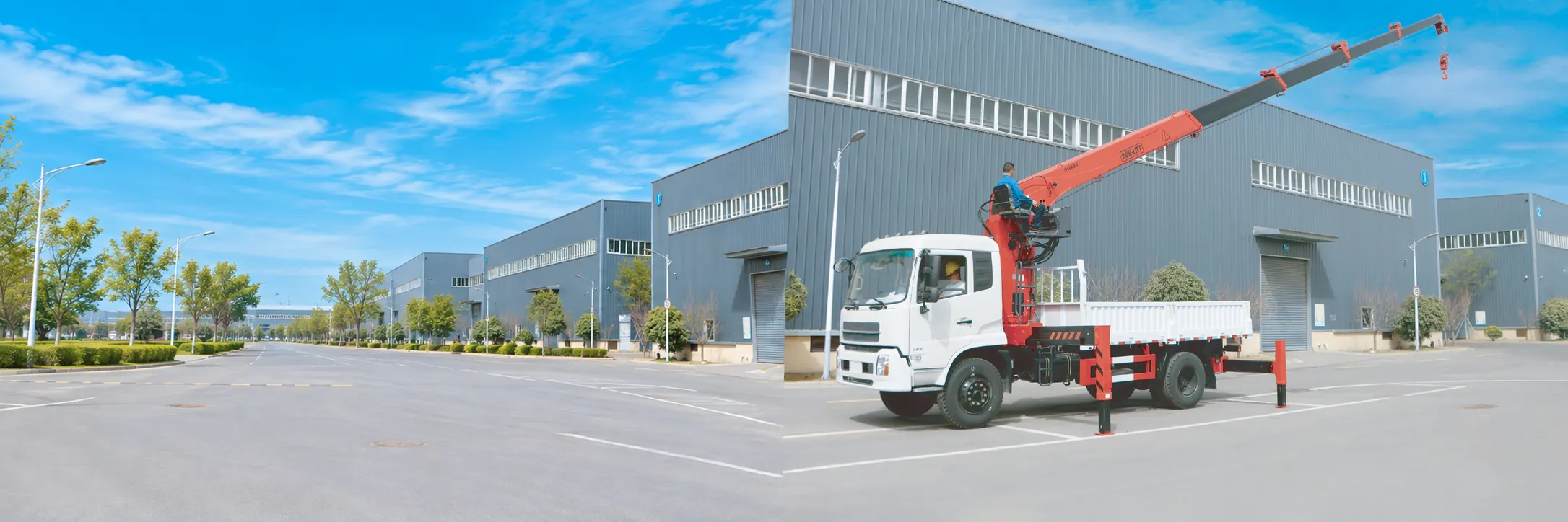

A ship crane is a crane fixed to the deck of a vessel that lifts cargo, stores and equipment between the ship, the quay and other boats. Most small and medium-sized ship cranes operating today are hydraulic: a pump delivers pressurised oil through a control valve into cylinders and hydraulic motors, which in turn raise the boom, rotate the crane and drive the winch. This guide explains, step by step, how a ship crane works, why its capacity changes with reach and on a moving deck, and in which applications it is typically used.
We have manufactured hydraulic cranes in Xuzhou, China, since 2003, including knuckle boom and telescopic marine cranes from 0.8 t to 25 t. All the figures quoted below are taken from our own technical drawings, so you can compare actual oil flows, operating pressures and load ratings rather than general marketing claims.
Key takeaways
- A hydraulic ship crane turns engine or electric power into oil flow and pressure. Flow sets the speed of each motion, and pressure sets the force.
- One control valve sends oil to the boom cylinders (luffing, folding, telescoping), the slewing motor and the winch motor.
- Capacity falls as the hook moves out, because the crane is limited by load moment: load times radius.
- On a ship the deck heels, rolls and pitches, so the load swings out of line and the real radius grows. Plan lifts with margin.
- Relief valves, holding valves on the cylinders, a winch brake and a load moment limiter keep the load under control if something goes wrong.
How does a ship crane work?
A hydraulic ship crane operates as a chain of energy conversions, beginning with a motor on board and ending with the load suspended from the hook. Each link in that chain corresponds to a physical component that you can identify on the crane itself:
- Power source. An electric motor or a diesel engine turns a hydraulic pump.
- Pump. The pump draws oil from the tank and delivers a steady flow, measured in litres per minute.
- Control valve. The operator moves a lever or a remote control, and the valve sends oil to the function selected.
- Actuators. Cylinders raise, fold and extend the boom; a hydraulic motor slews the crane; another motor turns the winch drum.
- Structure. The pedestal, slewing ring, column and boom carry the load and pass its forces into the deck.
- Return. Oil flows back through the valve to the tank, where it cools and settles before the pump draws it again.
The remaining sections follow the same sequence and then explain what changes on a moving deck. For the names and positions of every component, see our guide to ship crane parts and structure.
Where the power comes from
A hydraulic crane is indifferent to what drives its pump, provided that the pump delivers the required flow at the required pressure. On a vessel, the hydraulic energy usually comes from one of three sources:
- Electric power pack on deck. An electric motor, a pump and an oil tank combined in one unit and supplied from the ship’s generator. It is comparatively quiet, flexible to position, and operates independently of the main engine.
- Engine-driven pump (PTO). A pump mounted on a power take-off from the main or auxiliary engine. It uses power that is already available on board; however, the engine must be running, and variations in engine speed directly affect crane speed.
- The vessel’s existing hydraulic system. Many workboats and fishing vessels already operate a hydraulic ring main for winches and steering gear, and the crane can be connected to it, provided that sufficient spare flow is available.
Our marine crane product pages specify that the oil supply can come either from the vessel’s hydraulic system or from an electric or diesel power unit that we provide with the crane. The equivalent principle on road vehicles, including PTO selection and pump matching, is explained in our hydraulic crane for truck guide.
Whatever the power source, the crane’s technical drawing specifies exactly what it requires. Oil flow determines how quickly each motion operates, whereas system pressure determines how much force the cylinders and hydraulic motors can generate. The table summarises the corresponding figures from the drawings of six of our marine cranes.
| Model | Boom type | Max load | Recommended power | Oil flow | Pressure | Oil tank | Rotation |
|---|---|---|---|---|---|---|---|
| SQ08ZA3TJ+1 | Knuckle, winch | 800 kg | 3.5 kW | 8 L/min | 18 MPa | 20 L | 330° |
| SQ3.2ZA3TJ | Knuckle, winch | 3,200 kg | 15 kW | 25 L/min | 25 MPa | 60 L | 360° |
| SQ5ZA3TJ | Knuckle, winch | 5,000 kg | 22 kW | 35 L/min | 28 MPa | 100 L | 360° |
| SQ8ZA4TJ | Knuckle, winch | 8,000 kg | 25 kW | 40 L/min | 28 MPa | 160 L | 360° |
| SQ10ZA6TJ | Knuckle, winch | 10,000 kg | 30 kW | 40 L/min | 30 MPa | 160 L | 360° |
| SQ10SA4T | Telescopic | 10,000 kg | 37 kW | 63 L/min | 26 MPa | 200 L | 360° |
You can verify these numbers with a simple engineering rule: hydraulic power in kilowatts is approximately the flow in L/min multiplied by the pressure in MPa, divided by 60. For example, the SQ8ZA4TJ requires 40 × 28 ÷ 60, or approximately 18.7 kW of hydraulic power, and the drawing recommends a 25 kW drive, which provides a reserve for pump and motor efficiency losses. Consequently, if your vessel cannot supply that much power, the crane will operate slowly or stall under full load.

The control valve turns a lever into motion
The directional control valve is the crane’s hydraulic switchboard. It contains one section, or spool, for each function: main boom, outer boom, extensions, slewing and winch. When the operator moves a lever, the corresponding spool slides and opens a passage from the pump to one side of a cylinder or motor, and simultaneously from the opposite side back to the tank. Moving the lever in the other direction reverses the flow, so the boom lowers or the crane rotates the opposite way.
Lever travel also regulates speed. A small movement opens the spool only partially and allows a proportion of the flow through, which provides the precise control required to land a load gently on a rolling deck. With all levers in neutral, the oil circulates back to the tank and every function remains stationary. Our marine cranes can be operated with manual levers, from an elevated seat or by wireless remote control, and the hydraulic principle is identical in each configuration.
Cylinders: luffing, folding and telescoping
Hydraulic cylinders perform most of the lifting work. Oil pressure acts on the piston surface, and because force equals pressure multiplied by area, a cylinder with a large bore converts moderate pressure into an enormous pushing force. Three principal motions depend on cylinders:
- Luffing. The main boom cylinder raises and lowers the inner boom around its pivot on the column. Luffing up brings the hook closer to the crane and higher.
- Folding. On a knuckle boom crane, a second cylinder folds the outer boom around the knuckle joint. This lets the crane reach over a bulwark or into a hold, then fold into a compact package on deck.
- Telescoping. Extension cylinders inside the boom push the sections out to increase reach. Telescopic cranes gain their reach this way; knuckle boom cranes also use it on the outer boom.
The drawing of our SQ10SA4T telescopic marine crane demonstrates how the boom angle changes the lifting capability. With the boom extended to 9.02 m and positioned horizontally at 0°, the hook is located at a 9.0 m radius and the rating is 2,200 kg. Luffed up to 60°, the same boom brings the hook in to 4.4 m, while the rating increases to 4,300 kg; at 75°, the figures are 2.3 m and 7,000 kg. The crane has not become stronger; the load has simply moved closer to the slewing centre.
Which boom configuration suits a particular vessel is a separate question. Our article on the types of cranes used on a ship compares them, and the category pages list our knuckle boom marine cranes and telescopic boom marine cranes.
Slewing: how the crane turns
Slewing is the rotation of the entire crane around its pedestal. A hydraulic motor, usually connected through a reduction gearbox, drives a small pinion that engages a large gear ring on the slewing bearing. The bearing supports the crane’s weight and the overturning moment of the load, while still allowing the upper structure to rotate.
The rotation range is determined by the design: the drawings specify 330° for the compact SQ08ZA3TJ+1 and 360° for the larger models in the table above. When slewing stops, the motor’s brake or holding valve keeps the crane in position, which is particularly important at sea, because a heeling deck causes the suspended load to pull the boom downhill. Our guide to crane slewing drives explains the gear ring, worm and pinion layouts in more detail.
Hoisting: winch, wire rope and reeving
A crane without a winch lifts exclusively by moving its boom, so the hook height changes only when the boom moves. A crane equipped with a winch can raise and lower the hook independently, which is why most ship cranes include one: it enables the crew to lower a load deep into a hold or down to a boat alongside and then hoist it vertically.
The winch consists of a drum rotated by a hydraulic motor through a gearbox, together with a brake that holds the drum whenever the motor stops. The wire rope travels from the drum along the boom, over a sheave at the boom head and down to the hook. When the rope is reeved through a hook block with several parts of line, as in the cover photograph of this guide, each additional part shares the load, so the winch requires less line pull, although the hook moves correspondingly more slowly.
US longshoring rules for cranes that are part of a vessel’s permanent equipment, 29 CFR 1918.55, establish three practical requirements for the hoisting system. First, at least “three full turns of rope shall remain on ungrooved drums, and two full turns on grooved drums”. Second, brakes “shall be monitored during use”, and if they cannot hold the load, the crane must not be used. Third, where a crane is equipped with power-down capability, there must be “no free fall of the gear when a load is attached”.
The 55-second film below shows these components on our SQ8ZA4TJ, an 8 t knuckle boom marine crane with winch: the slewing motor, the control valve and hose guides on the column, the hydraulic winch drum and the operator’s lever stand.
Load moment: why capacity falls with reach
Load moment is the weight on the hook multiplied by its horizontal distance from the slewing centre, and every crane is ultimately limited by it. The steel structure, the slewing bearing and the deck foundation must all resist that moment; therefore, the further the hook moves outward, the less the crane is permitted to lift.
The load chart of our SQ5ZA3TJ 5 ton marine crane illustrates this relationship. It lifts 5,000 kg at 2.1 m, which corresponds to its rated moment of 10.5 t·m. At 4.45 m the rating is 2,350 kg, at 6.2 m it is 1,600 kg, and at the maximum 8.05 m reach it is 1,100 kg.
Example scenario (an illustration, not a customer record): a crew plans to lift a 1,500 kg pallet of stores from the quay with an SQ5ZA3TJ, and the pallet sits 6.2 m from the crane. The chart allows 1,600 kg there. If the hook, slings and shackles weigh 60 kg, the total is 1,560 kg, which is within the rating but leaves very little margin. If the vessel heels away from the quay, the load drifts outward and the radius grows. The safer plan is to move the vessel closer or land the pallet nearer the crane.
Our guides to the lifting moment of a crane and how to read a crane load chart explain the calculation in greater detail.
What changes when the crane is on a ship
The hydraulic principle is identical to that of a truck-mounted or quayside crane; however, a ship is constantly moving, and that motion changes how the forces act on the crane structure:
- Heel and trim. When the deck tilts, the load still hangs straight down. On the low side the hook ends up further from the crane than the radius shown on the boom, and the boom takes a side load it was not set up for.
- Roll, pitch and swell. Vessel motion makes the load swing and adds dynamic forces each time the rope snatches tight. Lifting from a boat that rises and falls alongside is the hardest case.
- The crane heels the ship. A load swung over the side shifts the vessel’s centre of gravity, and on a small boat or barge the heel can be large. Our barge crane guide shows a simple heel estimate.
- The deck must carry the crane. The pedestal passes the full moment into the deck structure. Regulation 6 of the UK Merchant Shipping lifting regulations requires lifting equipment to have adequate strength and stability, “having regard in particular to the stress induced at its mounting or fixing point”.
A load chart is normally calculated for a level crane base. Unless the crane supplier provides specific figures for heel, maintain a clear margin below the chart, reduce the speed of every motion, and suspend lifting whenever vessel motion makes the load difficult to control. Your naval architect should confirm deck strength and stability with the crane at full reach.
Safety devices in the hydraulic circuit
Because pressurised oil provides the crane’s muscle, most protective devices are valves within the hydraulic circuit. A typical hydraulic ship crane incorporates the following:
- Main relief valve. It opens when pressure reaches the set limit, so the pump cannot drive the system beyond its working pressure.
- Holding valves on the cylinders. Mounted directly on each cylinder, they lock the oil in place so the boom cannot drop if a hose bursts or pressure is lost. Our article on the hydraulic lock valve explains how they work.
- Load moment limiter. On most hydraulic cranes it senses the pressure in the main lifting cylinder and cuts off any motion that would increase the load moment once the limit is reached, while motions that reduce it usually stay available.
- Winch brake. A brake, usually spring-applied, holds the drum whenever the winch motor is not driven.
- Limit switches. They stop the hook from running into the boom head and the rope from paying out too far. The same US rule says limit switch bypass systems “shall be secured during all cargo operations”.
None of these devices replaces a trained and competent operator.
Where ship cranes are used
Large container terminals use dedicated quayside container cranes, whereas the hydraulic ship cranes described here handle the smaller, everyday lifting operations on and around vessels:
- Provisions, stores and spare parts on cargo vessels, lifted from the quay to the deck. Our deck crane guide covers outreach and stowage.
- Workboats and fishing boats, where a small knuckle boom crane handles nets, catch boxes, pots and equipment. See the boat crane guide.
- Barges and pontoons carrying building materials, pipes or dredging gear. The barge crane guide covers sizing and heel.
- Fixed pedestals on quays, jetties and steel platforms. See the pedestal crane guide.
- Harbour and dock work alongside other dock cranes, compared in what cranes are used at docks.
Our hydraulic marine cranes are built for harbours, barges, workboats and inshore vessels, and we size each one to the vessel it will work on.
Rules that apply to cranes on ships
In the UK, the general lifting regulations do not usually apply on board. The HSE overview of LOLER notes that “any lifting equipment used on ships is generally excluded because there are other provisions for the safety of this equipment under merchant shipping legislation”. Those provisions are the Merchant Shipping and Fishing Vessels (Lifting Operations and Lifting Equipment) Regulations 2006.
Two parts of those regulations follow directly from the working principle. Regulation 9 requires that lifting equipment carried on a ship whose safe working load varies with radius has “an accurate indicator, clearly visible to the operator”, showing the radius and the safe working load at that radius. Regulation 12 requires equipment exposed to conditions that cause deterioration, as on an open deck, to be thoroughly examined at least every 12 months, and every 6 months for lifting accessories and equipment for lifting persons, or under an examination scheme.
In the US, 29 CFR 1918.51 says the safe working load marked on the gear “shall not be exceeded” and that cargo gear must be inspected before each use.
Some vessels also need class approval for their deck cranes. Our hydraulic marine cranes are not certified by a classification society, so if your vessel or project needs it, confirm this with us before you order.
Frequently asked questions
How does a ship crane work in simple terms?
A motor drives a hydraulic pump, and the pump sends oil through a control valve to cylinders and motors. The cylinders raise, fold and extend the boom, one motor turns the crane and another drives the winch that raises and lowers the hook.
What powers a hydraulic ship crane?
An electric power pack on deck, a pump driven by the main or auxiliary engine, or the vessel’s own hydraulic system. The crane’s drawing gives the oil flow and pressure it needs, for example 35 L/min at 28 MPa for our SQ5ZA3TJ.
Why does a ship crane lift less at full reach?
Because the limit is load moment, which is load times radius. Our SQ5ZA3TJ lifts 5,000 kg at 2.1 m but only 1,100 kg at 8.05 m. Vessel heel can push the real radius beyond the planned one, so leave margin.
What is the difference between luffing and slewing?
Luffing raises or lowers the boom in a vertical plane, which changes the radius and the hook height. Slewing turns the whole crane around its pedestal, which moves the hook in a circle.
How often must a crane on a ship be examined?
Under the UK Merchant Shipping lifting regulations, a crane exposed to the weather needs a thorough examination at least every 12 months, and lifting accessories every 6 months, unless an examination scheme sets other intervals. Check the rules of your flag state and the crane manual as well.
How we compiled this guide
We compiled the flows, pressures, oil tank sizes, rotation angles and load ratings from the BOB-LIFT technical drawings of the SQ08ZA3TJ+1, SQ3.2ZA3TJ, SQ5ZA3TJ, SQ8ZA4TJ, SQ10ZA6TJ and SQ10SA4T, and from the SQ5ZA3TJ load chart. The power supply options, operating modes and class approval answer come from our live marine crane product pages. The quotations come from the official eCFR text of 29 CFR 1918.51 and 1918.55, from legislation.gov.uk and from hse.gov.uk. Achord Chan, Product Operations Director, reviewed the guide in November 2026. It does not replace your crane manual, your naval architect’s advice or the rules of your flag state.
Get a ship crane matched to your vessel
Send us your heaviest load, the reach you need, the deck space and how the vessel can supply hydraulic power. We will recommend a knuckle boom or telescopic marine crane and send its drawing and load chart, so your naval architect can check the deck and stability. Every crane carries a 12-month warranty on the whole machine, common spare parts leave the factory within 48 hours, and our service team answers within 12 hours. Contact us for a quotation.