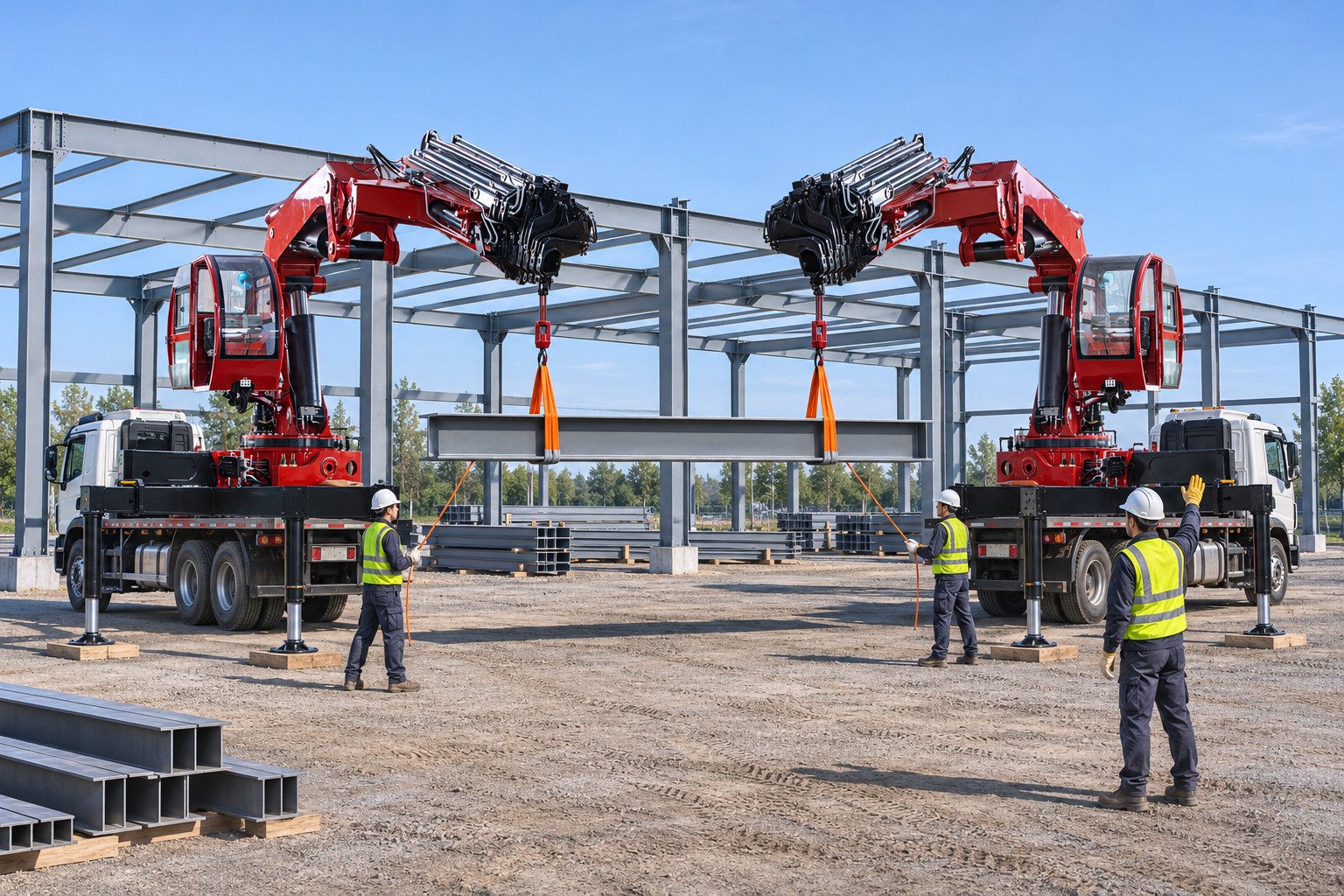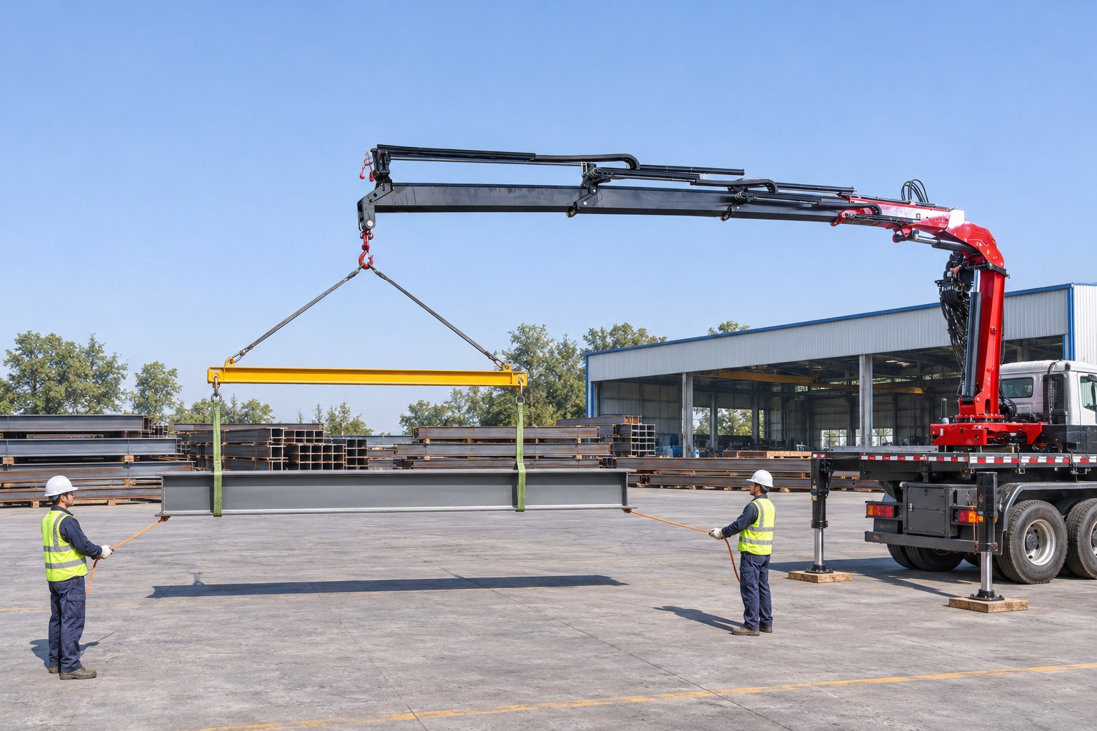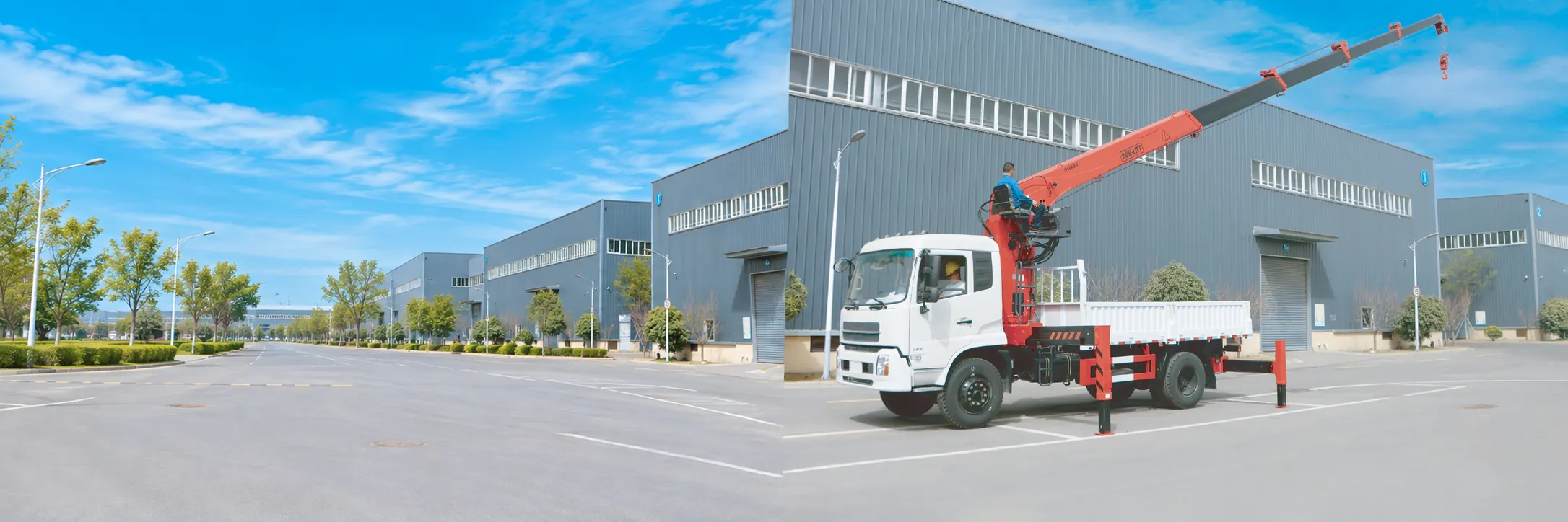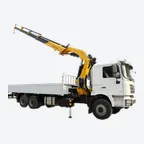

A lifting lug is a steel plate with a hole, welded or bolted to a load as a designed attachment point for a shackle or sling. Riggers also call it a pad eye or padeye. Each lug has a rated load and a permitted direction of pull. Three questions therefore determine whether a lift on lugs is acceptable: how steep the sling legs are, how many legs really carry the load, and whether every lug is pulled in its own plane.
BOB-LIFT has built truck mounted cranes in Xuzhou since 2003, and many loads our customers lift, such as pump skids, tanks, generators and steel frames, arrive with welded lugs. This guide explains the main types of lifting lugs and lifting points, the force each lug carries at common sling angles, the correct shackle connection and the checks to make before the lift. It finishes with a worked check of a 3,000 kg skid against two real BOB-LIFT load charts. We manufacture the cranes only; lugs come with the load, while shackles and slings are supplied by others.
Key takeaways
- A lifting lug or pad eye is a designed attachment point on the load, and its manufacturer or engineer sets both its rated load and the direction in which it may be pulled.
- The sling angle multiplies the force on each lug: at 60° from horizontal each leg carries about 1.15 times its share, and at 45° about 1.41 times.
- NSW rigging guidance says that two-, three- and four-leg slings “only ever rely on the capacity of 2 legs”, so check every lug for half the load at its angle.
- Pull each lug in the plane of its plate, connect it with a shackle whose pin passes through the hole, and never put a hook straight into a lug or eye bolt.
- In our example, a 3,000 kg skid alone fits a 6.3 t crane’s chart point by 10 kg, yet it fails once 60 kg of sling, shackles and master link are added.
What is a lifting lug or pad eye?
A lifting lug is a load-bearing plate fixed permanently to the object being lifted, with a hole sized for a shackle pin. Wikipedia’s entry describes the padeye as “made of steel plate with radius at one side” [5]. It explains that “lifting is done with the help of a D-shackle or sling, which fits into the hole of the padeye”. In addition, “there may be one or more circular plates (cheek plates) welded around the hole”, which thicken the plate where the pin bears.
The names overlap in everyday use. Lifting lug is the usual term on skids, tanks and machinery, whereas pad eye is common on ships and in oil and gas projects. A lifting point is the general term for any designed attachment on a load, including lugs, threaded fittings and cast-in inserts.
Types of lifting lugs and lifting points
Lifting points fall into five broad groups, which differ in how they attach to the load and in how well they tolerate an angled pull.
| Type | How it is fixed | Pull at an angle | Typical loads |
|---|---|---|---|
| Weld-on lug / pad eye | Welded to the structure, often with cheek plates | Only in the plane of the plate, as designed | Skids, tanks, steel frames, deck equipment |
| Bolt-on lug | Bolted to a flange or bracket | As designed; the bolts also carry the load | Machinery, removable covers, modules |
| Swivel lifting point (hoist ring) | Screwed into a tapped hole; the bail pivots and swivels | Turns to face the sling, but the angle still raises the force | Moulds, machined parts, dies |
| Eye bolt | Screwed into a tapped hole | Shoulder type only, in the plane of the eye, with reduced capacity | Motors, gearboxes, small machinery |
| Cast-in lifting insert or anchor | Embedded in precast concrete | As the insert’s manufacturer specifies | Precast panels, beams, blocks |
Shipping containers are a special case, because they have ISO corner castings instead of lugs. Riggers attach to them with twist-lock container lifting lugs or container hooks, and our guide on how to lift a shipping container with a crane covers those fittings together with the top-lift and bottom-lift rules.
Concrete lifting lugs, by contrast, are normally inserts cast into the element. For precast work on US construction sites, 29 CFR 1926.704 sets three strength margins. Inserts in tilt-up members must support “at least two times the maximum intended load”, and inserts in other precast members “at least four times”. The lifting hardware must support “at least five times the maximum intended load applied or transmitted to the lifting hardware”.
Why does the direction of the load matter?
A lug plate resists a pull in its own plane very well, but it bends easily when the pull acts across that plane. A sideways pull therefore loads both the plate and the weld at its base in bending, a condition the designer may not have considered. Wikipedia lists “dishing (out-of-plane buckling) failure of relatively thin lug plates that are laterally unrestrained” among the four failure modes observed in tests [5]. Importantly, it also notes that the design procedure in ASME BTH-1 “only allows for axially loaded lugs”.
The geometry of a multi-leg sling creates exactly this sideways component. Every inclined leg pulls its lug upwards and also inwards toward the point directly below the hook. On a rectangular skid with a lug at each corner, for example, the legs run diagonally toward the centre, so a lug welded parallel to the long edge is partly pulled across its plate. If the lugs do not point at the hook, ask the load’s manufacturer which direction they are rated for. Alternatively, use a spreader frame so that the legs hang vertically, as our spreader bar vs lifting beam guide explains.
How much force does each lug carry?
Each lug carries its share of the load multiplied by a factor for the sling angle. With θ measured between the sling leg and the horizontal, and with n legs sharing the load equally, the calculation is simple.
Force on each lug = load ÷ (n × sin θ).
The 1 ÷ sin θ term is the sling angle factor in the Brookhaven National Laboratory rigging workbook, which lists 1.000 at 90°, 1.155 at 60°, 1.414 at 45° and 2.000 at 30°. The workbook also advises: “avoid rigging loads where angle is less than 45°” [3]. Our crane rigging and slings guide gives the equivalent rule with the angle measured from vertical, together with the hitch types and sling capacity tables.
The more difficult question is the value of n. NSW Government’s Dogging and Rigging guide states that “two, three and four leg slings (wire, alloy chain or synthetic) only ever rely on the capacity of 2 legs” [2]. The reason, according to the guide, is that “you can never guarantee the load is equally distributed or balanced, or that sling leg lengths are matched perfectly”. In practice, a stiff skid on four lugs behaves like a table with one short leg, so two diagonal lugs can end up carrying most of the weight.

The chart shows why the two-leg case should be the design case. At 60°, each lug carries 866 kg if all four legs share the load equally, but 1,732 kg if only two legs do. At 45°, the corresponding figures rise to 1,061 kg and 2,121 kg. Consequently, every lug, shackle and sling leg needs a rating above the two-leg figure at the flattest angle you expect on the day.
How do you connect a shackle to a lifting lug?
Pass the shackle pin through the lug’s hole and seat the sling eye or chain link in the bow, so that the shackle lines up with the sling leg. The following points, drawn from the NSW and Brookhaven guidance, keep that connection in line.
- Use a marked shackle: NSW says shackles “must be branded with the working load limit (WLL)” and must not be used for lifting without that marking [1]. On US construction sites, 29 CFR 1926.251(f) prohibits loading a shackle above the limit on its “permanently affixed and legible identification markings”.
- Match the pin to the hole: A pin much smaller than the hole, or a lug much thinner than the shackle jaw, lets the shackle tilt. Where a narrow item sits on a pin, NSW advises packing the pin “with washers or ferrules to keep the load in the centre of the pin” [1].
- Keep the pull in line: NSW states that shackles “are designed to take vertical forces only”, meaning in line with the shackle body. Similarly, the Brookhaven workbook reduces the rated load of screw pin and bolt type shackles by 30% for a side load between 5° and 45°, and by 50% between 46° and 90° [3]. Where the shackle manufacturer publishes different figures, use those instead.
- Secure the pin: NSW recommends tightening screw pins by hand and then loosening them “by a quarter turn”. Where vibration could loosen a shackle left in place, it suggests mousing the pin to the body or using a safety-pin shackle.
- Never hook into the lug: NSW and Brookhaven both prohibit putting a hook directly into an eye bolt, and the same reasoning applies to a lug hole. Our crane hook guide covers what the hook end of the rigging needs.
Lifting lug vs eye bolt: what is the difference?
An eye bolt is a forged ring on a threaded shank that you screw into a tapped hole, whereas a lifting lug is part of the load’s structure. Eye bolts are far more sensitive to angle. According to the Brookhaven workbook, “non-shoulder eye bolts are only designed for vertical loads”, while shoulder eye bolts “must always be positioned to take the load in the plane of the eye” [3]. Moreover, shoulder eye bolts “should not be loaded at angles below 30” degrees unless the manufacturer approves it. The workbook’s capacity table shows how quickly the rating falls: a 1/2 inch shoulder eye bolt rated 1,840 lb for a vertical pull drops to 850 lb at 60° and 520 lb at 30°.
NSW adds two practical rules: “the pull should never be across the eye”, and where two eyebolts are used, “a pair of slings should be shackled into them” rather than one sling reeved through both [1]. A swivel hoist ring is a threaded lifting point whose bail pivots and rotates to face the sling. Brookhaven notes that, unlike eye bolts, its “rated capacity … is not reduced when loaded at angles”, although the extra tension from an angled leg must still stay within the ring’s rating.
Who designs and approves a welded lifting lug?
The design of a lug belongs to the load’s manufacturer or a competent engineer, not to the rigger or the crane supplier. According to Wikipedia, engineers check a padeye for bearing, shear, tension and Hertz contact stress at the hole, and for shear, tension, bending and combined stresses at the base, commonly following ASME BTH-1 or an equivalent analysis [5]. We deliberately give no plate or weld sizing formulas here. Instead, ask the load’s manufacturer for each lug’s rated load, the permitted sling angle and direction, and any proof test or weld inspection record.
Whether the regulations treat a lug as lifting equipment depends on how it is attached. In Great Britain, HSE describes a lifting accessory as equipment that attaches a load to the lifting equipment and “which is not a permanent part of the load (eg hooks, ropes, chains, shackles and eyebolts)” [4]. A welded pad eye therefore belongs to the load, while the shackles and any eye bolts you fit count as accessories. In the US, 29 CFR 1926.251(a)(4) requires “special custom design grabs, hooks, clamps, or other lifting accessories” to carry safe working load markings and a proof test “to 125 percent of their rated load” before use. For the ASME standards on below-the-hook devices, see our guide to below-the-hook lifting devices.
How should you inspect lifting lugs before a lift?
Under 29 CFR 1926.251(a)(1), rigging equipment “shall be inspected prior to use on each shift”, and defective equipment “shall be removed from service”. For the lugs themselves, look for the same warning signs that rigging guides list for eye bolts and shackles.
- Cracks in the plate, the cheek plates or the weld at the base. NSW warns that small microscopic cracks in deformed fittings “can extend under quite small loads and lead to complete failure” [1].
- An elongated or worn hole, or wear marks showing that a shackle has pulled at an angle. Brookhaven retires an eye bolt when wear reaches a tenth of any original dimension [3].
- Bent, twisted or dished plates, which typically indicate an earlier sideways pull.
- Heat damage, weld spatter or arc strikes, and any sign of grinding, re-welding or other alteration, all of which Brookhaven treats as reasons to remove an eye bolt from service [3].
- Corrosion at the weld toe or around the hole, especially on equipment that has stood outdoors or worked at sea.
- Missing information: if nobody can confirm the rating of a lifting point, NSW’s advice is clear: “If no information is provided about an eyebolt lifting point, the load should be lifted with slings” [1].

Example: a 3,000 kg skid on four pad eyes under a BOB-LIFT crane
Example scenario (an illustration, not a customer record): a contractor must lift a pump skid from a truck bed onto a plinth 4.4 m from the crane’s slewing centre. All load and rigging figures below are ASSUMED, while the crane figures come from BOB-LIFT drawings.
- Load: 3,000 kg, with four weld-on pad eyes at the corners of a 3.0 × 1.6 m pattern, so each pad eye sits 1.7 m from the centre of the pattern.
- Rigging: a four-leg chain sling, four shackles and a master link weighing 60 kg, which gives a gross load of 3,060 kg on the crane.
- Sling angle: legs 3.4 m long give about 60° from horizontal and put the hook 2.9 m above the pad eyes, whereas legs 2.4 m long give 45° and save 1.2 m of headroom.
- Force on each pad eye (two-leg design case): 3,000 ÷ (2 × sin 60°) = 1,732 kg, or 3,000 ÷ (2 × sin 45°) = 2,121 kg.
- Inward pull on each pad eye: about 866 kg at 60° and 1,500 kg at 45°, which is why the pad eyes must face the hook or carry a rating for that angle.
The longer legs are the better choice here if the crane has the hook height, because they reduce the force on each pad eye by about 390 kg. Next, we checked the gross load against the chart point at or beyond 4.4 m on two BOB-LIFT knuckle boom cranes.
| Check | SQ6.3ZA4 (6.3 t) | SQ8ZA5 (8 t) |
|---|---|---|
| Maximum capacity / lifting moment | 6,300 kg / 13.2 t·m | 8,000 kg / 16.7 t·m |
| Chart point used | 3,010 kg at 4,400 mm | 3,700 kg at 4,506 mm |
| Skid alone (3,000 kg) | Fits by 10 kg | Fits by 700 kg |
| Gross load with rigging (3,060 kg) | 50 kg over: does not pass | Passes with 640 kg spare |
| Next chart point outwards | 2,020 kg at 6,300 mm | 2,470 kg at 6,490 mm |
| Crane self weight | 2,180 kg | 3,250 kg |
The 6.3 t crane is the trap in this example. On paper, the skid fits its chart point at 4.4 m by 10 kg, but the sling and shackles push the gross load over the limit. OSHA’s crane rules define the load as the object plus “the load-attaching equipment, such as, the load block, ropes, slings, shackles, and any other ancillary attachment” (29 CFR 1926.1401). The 8 t crane passes at 4.5 m; however, neither crane could set the skid at 6 m, where their ratings fall to 2,020 kg and 2,470 kg. Our guides on how to read a crane load chart and safe working load explain chart points and why the rigging counts.
Every BOB-LIFT crane is listed with a load moment limiter, as our article on the lifting moment of a crane explains. A limiter, however, measures the total load on the crane; it cannot detect that one pad eye is taking twice its share or bending sideways. Our load moment indicator guide describes those limitations in more detail.
Before the lift, record the weight source, the sling angle, the rigging weight and the chart point in your crane lift plan. Under paragraph (o)(3)(i) of OSHA’s crane operation rule, the weight must come “from a source recognized by the industry (such as the load’s manufacturer)” or an equally reliable method. Then raise the skid a few centimetres, confirm that it hangs level and that no lug is twisting, and use a tagline wherever rotation would be hazardous, as paragraph (w) of the same rule requires. Finally, only the workers who hook, unhook or guide the load may stay within its fall zone, under 29 CFR 1926.1425(b).
Both cranes have their full drawings and load charts on the product pages: the SQ6.3ZA4 and the SQ8ZA5.
Frequently asked questions
What is the difference between a lifting lug and a pad eye?
There is no real difference: both are steel plates with a hole, welded or bolted to a load as a designed lifting point. Lifting lug is the usual name on skids and machinery, while pad eye is more common in marine and offshore work.
How do you calculate the force on a lifting lug?
Divide the load by the number of legs you rely on, then by the sine of the sling angle from horizontal. For a 3,000 kg load on two legs at 60°, that gives 3,000 ÷ (2 × 0.866), or about 1,732 kg per lug. This figure is the force on the lug, not its design, which remains the responsibility of the load’s manufacturer or engineer.
Do all four lugs share the load in a four-leg lift?
Not reliably. NSW rigging guidance says that two-, three- and four-leg slings only ever rely on the capacity of two legs, because nobody can guarantee equal sharing. Check each lug and leg for half the load at its angle, unless the lift uses an equalising arrangement designed for full sharing.
Can you use an eye bolt instead of a lifting lug?
Only where the load is designed for it and the direction of pull suits the eye bolt. A non-shoulder eye bolt takes vertical pulls only, and a shoulder eye bolt loses much of its capacity at an angle and must be pulled in the plane of the eye. Swivel hoist rings, by contrast, handle angled pulls without a reduced rating.
Does BOB-LIFT supply lifting lugs, shackles or slings?
No, we do not: we build truck mounted and marine cranes, lifting lugs come with the load from its manufacturer, and other suppliers provide shackles and slings. Send us the load weight, the lug pattern and your working radius, and we will check them against the load chart of the crane you are considering.
How we compiled this guide
The rigging guidance comes from the NSW Government Dogging and Rigging guide (shackles and eyebolts; shape of the load and connections) and from the Brookhaven National Laboratory Basic Rigging Workbook. The definition of a lifting accessory comes from HSE’s lifting equipment questions page, while the padeye description and failure modes come from Wikipedia. We quoted the rules from the official eCFR text of 29 CFR 1926.251, 1926.704, 1926.1401, 1926.1417 and 1926.1425, and read every source in November 2026. The forces follow from the sling angle formula and elementary geometry, and the crane figures come from the current BOB-LIFT SQ6.3ZA4 and SQ8ZA5 dimension drawings and load charts. The example uses clearly marked assumed weights and dimensions, and Achord Chan, Product Operations Director, carried out the editorial review before publication. This guide does not replace the load manufacturer’s lifting instructions, the crane’s operator’s manual or the regulations where you work.
Need a crane for loads with lifting lugs?
Tell us the load weight, the lug pattern and rating, the weight of the sling and shackles, and the radius at which the load must land. We will recommend a knuckle boom truck mounted crane or a telescopic crane and send its dimension drawing and load chart. If you buy the truck in China, we can fit the crane at our factory; if you buy it locally, we ship the crane, a local body builder fits it and we support the work remotely. Contact us for a quotation; every crane carries a 12-month warranty on the whole machine.