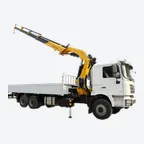

A load moment indicator (LMI) is the crane’s overload protection system. It senses the load and the radius, multiplies them into the load moment and compares the result with the load chart for the crane’s current set-up. It then shows the operator what percentage of rated capacity is in use. A load moment limiter does the same and then stops the motions that would push the crane further into overload. People often say “LMI” for both. In the United States, 29 CFR 1926.1416 requires one of these devices on most mobile cranes over 6,000 pounds built after March 29, 2003, and on articulating cranes built after November 8, 2011.
We have built truck mounted cranes in Xuzhou since 2003, and buyers frequently ask what the limiter on a crane actually measures, why it sometimes stops a lift that looked safe, and what to do when it reads wrong. This guide explains how an LMI works from sensor to cut-out, how to read the display, why the configuration setting matters more than anything else, and how to check the system before each shift. It also covers what the rules require, what the device cannot see, and the questions to ask before you buy.
Key takeaways
- An LMI senses load and radius, compares them with the stored load chart for the selected configuration and shows the percentage of rated capacity in use. A limiter also cuts out hoisting up, telescoping out and booming out or down.
- For mobile cranes, ISO 10245-2:2014 says the pre-warning must start between 90% and 97.5% of rated capacity, and the limiter must cut out between 100% and 110%.
- The configuration setting (outriggers, boom, reeving) is the most common source of wrong readings, because the controller normally cannot check that the selected mode matches the real crane.
- Check the system every shift. If it fails, US rules allow 30 calendar days to repair it, and in the meantime the load weight must come from a recognised source and be given to the operator before the lift.
- An LMI cannot see soft ground, wind, side loads or rigging weight that nobody entered. It supports the operator’s judgment, and it never replaces it.
What is a load moment indicator?
The US crane rule gives the clearest definition. In 29 CFR 1926.1401, a load moment (or rated capacity) indicator is “a system which aids the equipment operator by sensing (directly or indirectly) the overturning moment on the equipment, i.e., load multiplied by radius”. It compares this with the rated capacity and “indicates to the operator the percentage of capacity at which the equipment is working”, and “Lights, bells, or buzzers may be incorporated as a warning of an approaching overload condition”.
A load moment (or rated capacity) limiter senses the same thing. The difference is that “when the rated capacity is reached, it shuts off power to those equipment functions which can increase the severity of loading on the equipment, e.g., hoisting, telescoping out, or luffing out”. In Great Britain, the HSE code of practice for lifting equipment, L113, notes that rated capacity indicators “were previously known as automatic safe load indicators or moment load indicators”.
| Name | Also called | What it does | Stops the crane? |
|---|---|---|---|
| Load moment indicator | LMI, rated capacity indicator (RCI), safe load indicator | Senses load × radius and shows the percentage of rated capacity, with warning lights or a buzzer | No, it warns |
| Load moment limiter | Rated capacity limiter (RCL), overload limiter | Same sensing, then cuts the motions that increase the moment | Yes |
| Load weighing device | Load indicator | Measures and displays the weight on the hook | No |
| Automatic overload prevention device | Overload protection | The term OSHA lists for articulating cranes; stops an overload without necessarily showing a percentage | Yes |
The load moment itself is simply load multiplied by working radius, so 2 t at 5 m is 10 t·m. Our guide to the lifting moment of a crane explains the formula, the units and why the rated moment is not the same at every radius. This page concentrates on the device that watches that moment for the operator.
How does a load moment indicator work?
Every LMI follows the same three steps: sensors measure the crane’s state, a controller compares that state with the load chart, and the outputs warn the operator or stop the crane. The exact sensors vary by crane type and manufacturer, so the list below describes general practice rather than one product.
- Load. Measured directly by a load cell or load pin in the hook or rope path, or indirectly from hydraulic pressure in a lifting cylinder, which rises as the load or the radius grows.
- Boom angle. An angle sensor on the boom tells the controller how steeply the boom is raised.
- Boom length. On a telescopic boom, a length sensor reports how far the sections are extended.
- Radius. The controller works out the working radius from angle and length, so the radius on the screen is calculated, not measured.
- Slewing position. Where ratings differ over the front, side or rear of the truck, a slew sensor tells the controller which zone the boom is in.
- Configuration. The operator selects the outrigger setting, boom or jib combination and reeving, so the controller uses the matching load chart. Newer cranes may also sense outrigger position.
The controller then works out the moment, looks up the rated load for that radius and configuration, and divides one by the other. That percentage drives the display and, on a limiter, the valves that cut the dangerous motions. The diagram follows the signal from sensors to cut-out.

Why does the LMI need both boom angle and boom length?
Because the same boom angle gives very different radii and rated loads once the boom is extended. The table below comes from the boom-angle chart on the technical drawing of our SQ5SA4, a 5,000 kg telescopic truck mounted crane rated at 12.5 t·m. At a fixed angle of 40°, the four boom lengths give four radii and four rated loads.
| Boom length | Radius at 40° | Rated load at 40° | Radius at 50° | Rated load at 50° |
|---|---|---|---|---|
| 4.2 m | 2.6 m | 4,800 kg | 2.2 m | 5,000 kg |
| 6.8 m | 4.6 m | 2,200 kg | 3.8 m | 2,480 kg |
| 9.4 m | 6.7 m | 1,300 kg | 5.5 m | 1,580 kg |
| 12 m | 8.7 m | 860 kg | 7.3 m | 1,160 kg |
An angle sensor alone would see “40°” in every row, while the rated load falls from 4,800 kg to 860 kg. That is why a telescopic crane’s LMI reads length as well, and why 29 CFR 1926.1416(e)(3) lists a boom length indicator for telescopic booms “except where the rated capacity is independent of the boom length”. Our guide on how to read a crane load chart shows how to find these values yourself.
Example scenario (an illustration, not a customer record). An SQ5SA4 holds a pallet of ASSUMED weight 1,200 kg on ASSUMED 50 kg of slings, so the total load is 1,250 kg. With the 9.4 m boom at 40°, the chart allows 1,300 kg at 6.7 m, so the display shows about 96% and the warning is likely to be on. If the operator now telescopes to 12 m at the same angle, the rating drops to 860 kg, about 145% of capacity, and a limiter stops telescoping out long before the boom gets there. Lowering the 9.4 m boom to 30° instead moves the hook to 7.6 m, where the chart allows 1,150 kg, about 109%, so booming down is stopped as well. Retracting the boom or raising it brings the moment back down.
What happens when the load approaches the limit?
Most systems work in stages: normal work, a pre-warning, and then an overload response. The international standard for limiting and indicating devices on mobile cranes is ISO 10245-2:2014. It says the rated capacity indicator “shall give a warning both visually and acoustically of the approach to the rated capacity starting between 90 % and 97,5 %” [1]. The limiter “shall be set to override the crane controls at values between 100 % and 110 % of the rated capacities”, and “All sensor tolerances within the system must be considered when determining the accuracy of the system”.

For truck mounted loader cranes, Safe Work Australia says vehicle loading cranes manufactured after 2003 should have a load indicator that will “warn the crane operator when the load exceeds 90 per cent of the rated capacity”. It should also “give a separate and different warning to the 90 per cent load warning to the crane operator and people near the crane if the rated capacity is exceeded”.
When the limiter acts, ISO 10245-2 lists the motions it should normally override on a mobile crane: “derricking out”, “derricking in”, “hoisting” and “telescoping out”. For slewing, the standard says that “where capacity decreases by slewing, power to the slew function in the direction of continued motion will be deactivated”. The OSHA definition adds that “functions which decrease the severity of loading on the equipment remain operational, e.g., lowering, telescoping in, or luffing in”. Your crane’s manual is the final word on which motions stop and how to recover, so read that section before the first lift.
How do you read an LMI display?
A display is designed to be read at a glance, and ISO 10245-2 requires that “All devices with readouts shall be legible from the operator’s station”. The screen below is a real limiter display on a BOB-LIFT telescopic crane. It shows 5.17 t on the hook against 5.00 t rated, at a radius of 2.47 m and a boom angle of 50.8°, so the bar reads 103.3% and the crane is slightly over its rated capacity.

- Percentage bar. The quickest check. Green means room to work, and the bar turns warning-coloured as it nears 100%.
- Actual load. What the sensors calculate is on the hook, including the hook block and rigging the system can feel.
- Rated load. The chart value for the current radius and configuration, which changes as the boom moves.
- Radius and angle. Calculated geometry; compare it with a tape measurement during your checks.
- Boom length and height. Shown on telescopic cranes, where the rating depends on them.
- Mode or configuration code. The set-up the controller is using. If this is wrong, every other figure is wrong too.
Our telescopic product pages list a load moment limiter with a live display, as on the telescopic boom truck mounted cranes range. For how a telescopic boom is built and why its rating changes so much with length, see our guide to the telescopic boom crane.
Is the LMI different on knuckle boom and telescopic cranes?
The principle is identical, but the geometry the controller must know is different. A telescopic crane’s radius comes from one boom angle and one boom length. A knuckle boom crane folds at a second joint and often has several hydraulic extensions, so its load chart is usually written against radius rather than angle. Many manufacturers simplify the protection to an overload limit on the lifting system. Our guide to what a knuckle boom crane is shows how the boom folds.
The US rule reflects this split. Under 29 CFR 1926.1416(e)(4)(ii), articulating cranes “manufactured after November 8, 2011 must have at least one of the following: automatic overload prevention device, load weighing device, load moment (or rated capacity) indicator, or load moment (rated capacity) limiter”. Paragraph (a)(1) also says the boom angle, jib angle and boom length indicator requirements “do not apply to articulating cranes”. So a knuckle boom crane may legitimately have no percentage display at all, provided it has one of the listed devices.
Either way, the operator still needs the chart. The Irish Health and Safety Authority’s lorry loader crane information sheet (2018) lists “Vehicle instability caused by overloading” first among the most common causes of lorry loader crane accidents. It asks operators to “know and understand the safe working load of the crane in the different positions”. Every BOB-LIFT crane is listed with a load moment limiter, as our article on the lifting moment of a crane explains, and each model in our knuckle boom truck mounted cranes range has its own load chart.
Why is the configuration setting so important?
Because the LMI trusts what it is told. A crane on fully extended outriggers has a much higher rating than the same crane on short-jacked outriggers or with a different boom combination. If the operator selects the wrong mode, the controller compares the real load with the wrong chart. ISO 10245-2 requires “a precise and continuous indication of the crane configuration for which the rated capacity limiter/indicator has been set”, and it says that no unintended change of the configuration selection shall be possible. Its note is the warning every operator should remember: “Normally there is no check (automatic plausibility check), whether the selected configuration corresponds with the real configuration”.
Outrigger sensing helps on newer equipment. For equipment manufactured after November 8, 2011, 29 CFR 1926.1416(e)(5)(i) lists an “Outrigger/stabilizer position (horizontal beam extension) sensor/monitor” where the crane has outriggers. If it is not working, “The operator must verify that the position of the outriggers or stabilizers is correct (in accordance with manufacturer procedures) before beginning operations requiring outrigger or stabilizer deployment”. Use this short routine at every set-up:
- Set the outriggers exactly as the load chart you intend to use requires, on firm ground with suitable pads.
- Select the matching configuration on the LMI and read the code back against the chart or the code list.
- Enter any setting the system asks for, such as the number of rope falls or an attachment.
- Lift the hook block clear and check that the actual-load reading is plausible before you attach a load.
- Re-select the mode whenever you change outriggers, extensions, reeving or attachments.
Our guide to crane outriggers and ground bearing pressure explains how outrigger forces and pads are worked out, which the LMI does not do for you.
How do you check and calibrate a load moment indicator?
Check it every shift, and have its accuracy verified at the intervals the manufacturer sets. The shift inspection in 29 CFR 1926.1412(d)(1)(xiv) covers “Safety devices and operational aids for proper operation”. The annual inspection in (f)(2)(v) goes further: “Safety devices and operational aids for proper operation (including significant inaccuracies)”. HSE L113 gives “malfunction, eg of a rated capacity indicator” as an example of a fault that regular inspection can detect.
- Self-test at start-up. Watch the display run its check and confirm there are no fault messages. ISO 10245-2 requires that the indicator’s operation, “but not necessarily its accuracy, can be checked without applying loads to the crane”.
- Check warnings. Confirm that the lights and buzzer work, as your manual describes.
- Compare geometry. With the boom at a known position, compare the displayed angle and radius with what you see or measure.
- Check a known load. When a load of known weight is available, compare it with the actual-load reading.
- Record and report. Write the result in the pre-use check and report any doubt before lifting.
ISO 10245-2 also sets accuracy targets for mobile cranes. Indicators are allowed to err only on the safe side, so the crane looks heavier, steeper or further out than it really is.
| Reading | Accuracy in ISO 10245-2:2014 |
|---|---|
| Load indicator | Indicated load between 100% and 110% of the actual load, when the load exceeds 75% of rated capacity |
| Boom angle, 65° or more | 0° / −2° from the actual angle |
| Boom angle, below 65° | 0° / −3° from the actual angle |
| Boom length (telescopic) | ±2% of the actual length |
| Radius | −0 to +10% of the actual radius |
| Rated capacity limiter | Operates between 100% and 110% of rated capacity during calibration and testing, at the lowest working speed |
Calibration belongs to a competent technician with the manufacturer’s procedure and known test weights. After any repair or adjustment to a safety device or operational aid, 29 CFR 1926.1412(c) requires an inspection by a qualified person before the crane is used again. The truck mounted crane inspection checklist covers the rest of the daily check, and our guide to the crane load test explains how proof loads are handled.
What do the rules say if the LMI stops working?
In the United States, a load moment indicator or limiter is a Category II operational aid under 29 CFR 1926.1416(e). The basic rule in paragraph (b) is that “Operations must not begin unless the listed operational aids are in proper working order”, except where the device is being repaired and the employer uses the temporary alternative measures. If the device fails during a lift, paragraph (c) says “the operator must safely stop operations until the temporary alternative measures are implemented or the device is again working properly”.
- Repair time. Category II aids “must be repaired no later than 30 calendar days after the deficiency occurs”. If parts were ordered within 7 days and arrive too late, the repair must be done within 7 days of receipt.
- Which cranes. Equipment other than derricks and articulating cranes “manufactured after March 29, 2003 with a rated capacity over 6,000 pounds” needs a load weighing device, an LMI or a limiter. Articulating cranes need one of the four listed devices if built after November 8, 2011.
- Temporary measure. “The weight of the load must be determined from a source recognized by the industry (such as the load’s manufacturer) or by a calculation method recognized by the industry”. The rule adds: “This information must be provided to the operator prior to the lift”.
- Reporting. Under 1926.1417(j), the operator reports the needed repair in writing, and the employer tells affected employees at the start of each shift.
The March 2003 date has a history. OSHA’s 2008 proposal in the Federal Register explains that this was “the date when ASME B30.5 first called for all mobile cranes with a rated capacity over 6,000 pounds to be equipped with load weighing devices”. Outside the US, check your own rules. In Europe, Annex I section 4.2.2 of the Machinery Directive 2006/42/EC covers machinery “with a maximum working load of not less than 1 000 kilograms or an overturning moment of not less than 40 000 Nm”. Such machinery must have devices that warn the driver and prevent dangerous movements on overload. HSE L113 says that where there is “a significant risk of overturning and/or overloading”, rated capacity indicators and limiters should be provided.
Why must you never bypass a load moment limiter?
Because the cut-out is the last barrier before overturning or a structural failure, and disabling it removes that barrier at exactly the moment it is needed. US rules are blunt: under 29 CFR 1926.1417(k), “Safety devices and operational aids must not be used as a substitute for the exercise of professional judgment by the operator”. Paragraph (o)(1) adds that “The equipment must not be operated in excess of its rated capacity”.
Many limiters have an override key, but it is meant for narrow tasks. ISO 10245-2 notes that “An override key for b) can be provided within the reach of the operator (for derricking in a suspended load)”. It adds that the indicator “shall continue its function when the rated capacity limiter is overridden during testing, rigging, or de-rigging”. Use an override only as your manual describes, never to finish a lift the crane has refused. The HSA sheet also asks owners to make sure “that any interlocks or safety devices are properly maintained”. Our guide to crane accidents and how to prevent them shows where overloads fit among the other causes.
What can a load moment indicator not see?
An LMI compares the crane’s state with the load chart, and the chart assumes the conditions printed in its notes. ISO 10245-2 notes that rated capacities “do not take into consideration adverse operating conditions, e.g. high winds, multilift operation, etc.” These are the gaps to cover with planning:
- Ground and outrigger support. The device does not know whether the ground under a pad is about to sink.
- Level. A tilted crane carries the load further out than the calculated radius.
- Wind. Under 29 CFR 1926.1417(n), “The competent person must adjust the equipment and/or operations to address the effect of wind, ice, and snow on equipment stability and rated capacity”. See our guide to crane wind speed limits.
- Side loads and dynamic loads. Dragging a load sideways, swinging it or stopping sharply adds forces that a load chart does not cover.
- Rigging weight and attachments. The OSHA definition of load includes “the load block, ropes, slings, shackles, and any other ancillary attachment”. If the system is not set for an attachment, the rating it uses may be wrong.
- Unknown load weight. Under 1926.1417(o)(3)(ii), an operator may use the LMI to check whether the load “exceeds 75 percent of the maximum rated capacity at the longest radius that will be used”. If it does, the lift cannot continue until the weight is verified from a recognised source.
These limits are why a lift needs a plan as well as a working limiter. Our crane lift plan guide sets out the steps, and the safe working load guide explains why the whole rigging chain, not only the crane, must be within its rating.
LMI vs anti-two-block device vs boom angle indicator vs boom stops
Crane overload protection devices are often confused, but each one watches something different. The LMI watches load against radius, the anti-two-block device watches the gap under the boom head, the angle indicator shows the boom angle, and a boom stop physically limits how far the boom can be raised.
| Device | What it watches | What it does | US rule |
|---|---|---|---|
| Load moment indicator / limiter | Load × radius against the load chart | Warns; a limiter stops moment-increasing motions | 29 CFR 1926.1416(e)(4) |
| Anti-two-block device | Hook block rising into the boom head | Stops hoist up, telescope out, boom down | 29 CFR 1926.1416(d)(3) |
| Boom angle or radius indicator | Boom angle relative to horizontal | Shows angle or radius to the operator | 29 CFR 1926.1416(e)(1) |
| Boom stop | Maximum boom angle | Restricts the boom from moving past it and toppling backward | 29 CFR 1926.1415(a)(2) |
The rules require boom stops “except for derricks and hydraulic booms”, so on a hydraulic truck mounted crane the cylinders and their end stops set the maximum angle. Our article on the maximum angle for a crane boom covers that question. The anti-two-block device guide explains why an LMI cannot prevent two-blocking.
What should you ask about the LMI when you buy a crane?
Ask the manufacturer which overload device is fitted to the exact model and configuration you are quoted, and have it named in the quotation and the operator’s manual. These questions cover the points that matter in daily use:
- Is it an indicator, a limiter or both, and which motions does it stop at the limit?
- Does it have a live display, and which values does the display show?
- How is the configuration selected, and does the crane sense outrigger position?
- What is the daily check, and how often should the system be calibrated, by whom?
- Is there an override, what is it for, and how is it controlled?
- Which sensors and spare parts are recommended, and how is a fault shown?
Every BOB-LIFT crane is listed with a load moment limiter, and our telescopic product pages list a live display with it. For anything else, ask us to confirm in writing what is fitted to the model you are quoted. The rated loads it protects come from each model’s load chart, and our guide on how to calculate crane capacity shows how to size the crane before you rely on the limiter.
Frequently asked questions
What does LMI mean on a crane?
LMI stands for load moment indicator. It senses the load and the radius, compares them with the crane’s load chart and shows the percentage of rated capacity in use. In daily speech, LMI is also used for a load moment limiter, which stops the motions that increase the moment once the rating is reached.
What is the difference between an LMI and an RCL?
An LMI, or rated capacity indicator, only measures and warns. A rated capacity limiter (RCL), or load moment limiter, also cuts out hoisting, telescoping out and booming out or down when the rated capacity is reached, while lowering and telescoping in normally stay available.
At what percentage does a crane LMI warn?
For mobile cranes, ISO 10245-2:2014 says the pre-warning must start between 90% and 97.5% of rated capacity, and the limiter must act between 100% and 110%. For vehicle loading cranes, Safe Work Australia recommends a warning above 90% and a separate warning above 100%. Your manual gives your crane’s settings.
Can you use a crane if the LMI is not working?
Under US rules, only while it is being repaired, which must happen within 30 calendar days. Meanwhile, the weight of every load must be determined from a recognised source or calculation and given to the operator before the lift. Stricter manufacturer measures, if any, must be followed.
Why does my LMI show the wrong load?
The most common reason is a configuration that does not match the crane, such as the wrong outrigger mode, boom combination or reeving. Other causes include a damaged sensor or cable, a cold or contaminated hydraulic reading, or a system due for calibration. Stop, check the set-up and report it if the reading remains doubtful.
How we compiled this guide
We quoted the US rules from the official Code of Federal Regulations text of 29 CFR 1926.1401, 1926.1412, 1926.1415, 1926.1416 and 1926.1417 on govinfo.gov, revised as of July 1, 2025. The 2003 background comes from OSHA’s 2008 proposed rule (73 FR 59714). The warning and accuracy values come from ISO 10245-2:2014 (preview pages), Safe Work Australia’s vehicle loading cranes information sheet (December 2015) and the HSA Ireland lorry loader crane information sheet (May 2018). The British and European wording comes from HSE L113 (second edition, 2014) and Annex I of the Machinery Directive on legislation.gov.uk. The boom-angle table comes from the current BOB-LIFT technical drawing of the SQ5SA4, and the device statements come from our live product pages. The sensor descriptions are general practice, not taken from a single source. The diagrams are our own work, and Achord Chan, Product Operations Director, reviewed the guide in November 2026. It does not replace your crane’s manual or local regulations.
Need a truck mounted crane with a load moment limiter?
Tell us the loads, the working radius and lifting height, and the country where the crane will operate. We will recommend a telescopic or knuckle boom truck mounted crane and send its dimension drawing and load chart, and you can ask us to name the overload device in the quotation. Every crane carries a 12-month warranty on the whole machine, common spare parts leave the factory within 48 hours, and our service team answers within 12 hours. Contact us for a quotation.